小波去噪演演算法的簡易實現及其擴充套件(小波銳化、高斯拉普拉斯金字塔去噪及銳化)之一。
早年就接觸過小波的概念,那個時候看什麼小波十講這類的,看的可真謂雲裡霧裡,一大堆數學公式,頭大的要死。做去噪的時候也看很多人說小波去噪演演算法效果不錯,不過網路上有的都是matlab程式碼,而matlab的小波包裡的函數是已經寫好的內嵌函數,是無法看到程式碼的。因此,一直以來,也從未想過自己動手寫個小波去噪之類的效果。
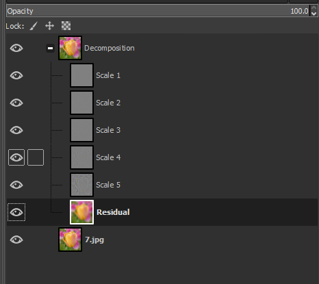
偶爾翻閱了一下GIMP軟體的選單,再次看到了在其Filters-->Enhance選單下有個wavelet-decompose選單,點選一下,發現原影象是沒有任何增強的效果的,但是在其圖層介面裡增加了一些列的圖層,如下圖所示:

後面搜尋一些參考資料,大概明白了他的意識這個做分解是為後續的增強做鋪墊的,因為他分解成了多個層後,可以單獨對每個層進行一些特別的處理,GIMP官方的檔案對其說明如下:
This filter decomposes the active layer or selection into several layers, named 「scales」, each of them containing a particular set of details. Finest details are in first layers and they become larger until you get to the last one, at bottom. This last layer is called 「residual」 and holds what is left after all detail layers have been removed; it represents the global contrast and colors of the image.
Each of scale layers are set to combine using the Grain Merge layer mode. This means that pixels that have a 50% value will not affect the final result. So, painting a wavelet scale with neutral gray (R:50% G:50% B:50%) will erase details.
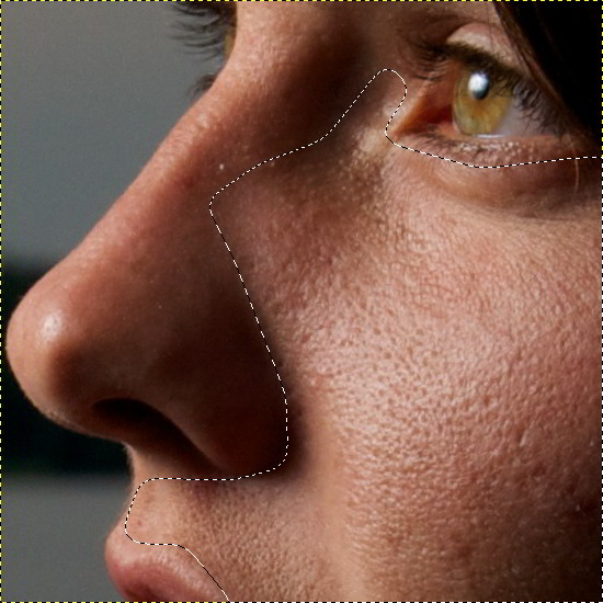
Wavelet-decompose is a wonderful filter for skin smoothing and retouching, removing blemishes, wrinkles, spots from your photos. It can be used also for sharpening and local contrast enhancement and for removing stains, colors, tones. All this is well explained in tutorials mentioned above.
這個幫助最後提到這個分解可以用於面板光滑、磨皮、移除瑕疵、斑點等,或者做銳化以及區域性增強等等功能。
似乎很是強大。
仔細看看GIMP分解後的圖,我們發現他將影象分解為了多個圖層,圖層的數量取決使用者介面的引數,比如選擇5層,他實際上是生成了6個圖層,額外增加了一個特殊的Residual(殘餘)層,我們試著嘗試解析他的程式碼。
在GIMP的原始碼裡搜尋wavelet,可以發現gimp-master\plug-ins\common這個目錄下有個wavelet-decompose.c檔案,再開啟這個檔案,稍微分析下這個程式碼,發現其中需要一個非常核心的函數:wavelet_blur,這個函數確沒有在gimp-master這個資料夾裡,而是在gegl-master這裡。wavelet_blur函數又涉及到一個wavelet-blur-1d的檔案。
得益於早年我翻譯和抽取過很多GIMP的函數,以及自己對影象處理本身演演算法的瞭解,雖然GIMP的程式碼寫的很晦澀,但是拼接多年的經驗,還是成功的把這個程式碼抽取出來。下面簡要的分析下:
在wavelet-decompose.c裡有一段核心的東西如下:
 1   for (id = 0 ; id < wavelet_params.scales; id++)
 2     {
 3       GimpLayer *blur;
 4       GimpLayer *tmp;
 5       gchar      scale_name[20];
 6
 7       gimp_progress_update ((gdouble) id / (gdouble) wavelet_params.scales);
 8
 9       scale_layers[id] = new_scale;
10
11       g_snprintf (scale_name, sizeof (scale_name), _("Scale %d"), id + 1);
12       gimp_item_set_name (GIMP_ITEM (new_scale), scale_name);
13
14       tmp = gimp_layer_copy (new_scale);
15       gimp_image_insert_layer (image, tmp, parent,
16                                gimp_image_get_item_position (image,
17                                                              GIMP_ITEM (new_scale)));
18       wavelet_blur (GIMP_DRAWABLE (tmp), pow (2.0, id));
19
20       blur = gimp_layer_copy (tmp);
21       gimp_image_insert_layer (image, blur, parent,
22                                gimp_image_get_item_position (image,
23                                                              GIMP_ITEM (tmp)));
24
25       gimp_layer_set_mode (tmp, grain_extract_mode);
26       new_scale = gimp_image_merge_down (image, tmp,
27                                          GIMP_EXPAND_AS_NECESSARY);
28       scale_layers[id] = new_scale;
29
30       gimp_item_set_visible (GIMP_ITEM (new_scale), FALSE);
31
32       new_scale = blur;
33     }
34
35   gimp_item_set_name (GIMP_ITEM (new_scale), _("Residual"));
明顯這個迴圈就是要生成各個圖層的內容的。
第14行從new_scale層拷貝資料到tmp,然後第18行進行一個wavelet_blur得到Blur影象 ,注意那個模糊的最後一個引數,是二的整數次冪的變化,即隨著層數的增加,由1->2->4->8->16,依次類推,至於這個模糊後續再繼續詳解。
第25行設定tmp層的混合模式為grain_extract, 第26行執行圖層向下混合並將資料儲存到new_scale中,這個時候就是相當於把Blur影象和tmp影象進行grain_extract混合,這個混合模式PS中是沒有的,我們可以在GIMP的程式碼gimpoperationlayermode-blend.c中找到其程式碼:
void
gimp_operation_layer_mode_blend_grain_extract (GeglOperation *operation,
                                               const gfloat  *in,
                                               const gfloat  *layer,
                                               gfloat        *comp,
                                               gint           samples)
{
  while (samples--)
    {
      if (in[ALPHA] != 0.0f && layer[ALPHA] != 0.0f)
        {
          gint c;

          for (c = 0; c < 3; c++)
            comp[c] = in[c] - layer[c] + 0.5f;
        }

      comp[ALPHA] = layer[ALPHA];

      comp  += 4;
      layer += 4;
      in    += 4;
    }
}
即兩者相減然後加上0.5,注意這裡的資料範圍都是[0,1]。
第28句就是把new_scale賦值給當前層,第32句的複製又把剛剛模糊後的資料賦值給new_scale。
當下一次迴圈開始的時候,新的new_scale實際上已經是上一次模糊後的值了,這個必須得到重視。
第35句則是把最後一次模糊後的值直接新增一個新的層中,並把該層命名為Residual。、
整個的過程其實就是這麼簡單,我們可以看到除了最後一層外,其他的層其實都是那上一次模糊後的值減去這次模糊後的值,所以他們相間後就得到了不同尺度的細節資訊。
下面我們來看看這個函數中最為核心的wavelet_blur是怎麼回事,在wavelet-blur.c中,並沒有給出什麼具體的程式碼實現,只有這樣一段函數:
static void
attach (GeglOperation *operation)
{
  GeglNode *gegl   = operation->node;
  GeglNode *input  = gegl_node_get_input_proxy (gegl, "input");
  GeglNode *output = gegl_node_get_output_proxy (gegl, "output");

  GeglNode *vblur  = gegl_node_new_child (gegl,
                                          "operation", "gegl:wavelet-blur-1d",
                                          "orientation", 1,
                                          NULL);

  GeglNode *hblur  = gegl_node_new_child (gegl,
                                          "operation", "gegl:wavelet-blur-1d",
                                          "orientation", 0,
                                          NULL);

  gegl_node_link_many (input, hblur, vblur, output, NULL);

  gegl_operation_meta_redirect (operation, "radius", hblur, "radius");
  gegl_operation_meta_redirect (operation, "radius", vblur, "radius");

  gegl_operation_meta_watch_nodes (operation, hblur, vblur, NULL);
}
這些都是一些大型軟體喜歡用的東西,看的是暈頭轉向,核心的就是兩個gegl_operation_meta_redirect呼叫,其實一看後面的引數也就知道了,先水平模糊,然後在垂直模糊,我們直接調轉到對應的真正描述演演算法的部分去,即wavelet-blur-1d.c檔案中。
開啟wavelet-blur-1d.c檔案,可以快速的看到有wav_hor_blur以及wav_ver_blur2個函數名,很明顯,這個驗證了我們前面的猜測。兩個函數的函數體的內容基本完全相同。我們以wav_hor_blur為例:
static void
wav_hor_blur (GeglBuffer          *src,
              GeglBuffer          *dst,
              const GeglRectangle *dst_rect,
              gint                 radius,
              const Babl          *format)
{
  gint x, y;

  GeglRectangle write_rect = {dst_rect->x, dst_rect->y, dst_rect->width, 1};

  GeglRectangle read_rect = {dst_rect->x - radius, dst_rect->y,
                             dst_rect->width + 2 * radius, 1};

  gfloat *src_buf = gegl_malloc (read_rect.width * sizeof (gfloat) * 3);
  gfloat *dst_buf = gegl_malloc (write_rect.width * sizeof (gfloat) * 3);

  for (y = 0; y < dst_rect->height; y++)
    {
      gint offset     = 0;
      read_rect.y     = dst_rect->y + y;
      write_rect.y    = dst_rect->y + y;

      gegl_buffer_get (src, &read_rect, 1.0, format, src_buf,
                       GEGL_AUTO_ROWSTRIDE, GEGL_ABYSS_CLAMP);

      for (x = 0; x < dst_rect->width; x++)
        {
          wav_get_mean_pixel_1D (src_buf + offset,
                                 dst_buf + offset,
                                 radius);
          offset += 3;
        }

      gegl_buffer_set (dst, &write_rect, 0, format, dst_buf,
                       GEGL_AUTO_ROWSTRIDE);
    }

  gegl_free (src_buf);
  gegl_free (dst_buf);
}
整體其實沒啥,前面的一堆就是分配記憶體,搞定讀寫的區域範圍,核心的演演算法部分又是呼叫wav_get_mean_pixel_1D 函數,所以又只能跳轉到wav_get_mean_pixel_1D 這個函數中:
static inline void
wav_get_mean_pixel_1D (gfloat  *src,
                       gfloat  *dst,
                       gint     radius)
{
  gint     i, offset;
  gdouble  weights[3] = {0.25, 0.5, 0.25};
  gdouble  acc[3]     = {0.0, };

  for (i = 0; i < 3; i++)
    {
      offset  = i * radius * 3;
      acc[0] += src[offset]     * weights[i];
      acc[1] += src[offset + 1] * weights[i];
      acc[2] += src[offset + 2] * weights[i];
    }

  dst[0] = acc[0];
  dst[1] = acc[1];
  dst[2] = acc[2];
}
這個函數就非常明朗了,要幹啥也一清二楚。仔細看程式碼,發現原來他只是一個3個畫素求加權的過程,中心點的權重佔了一半,左右2個畫素的權重各佔1/4,。
但是注意這裡的座標偏移即offset變數,他是使用的i * radius * 3,乘以3是因為3通道,而乘以Radius則,表示他的取樣並不是相鄰一個畫素的左右取樣,而是相鄰Radius個畫素。
注意,因為在wav_hor_blur函數中,對src源資料指標已經有了一個向左radius的偏移,所以這裡的i=0時的座標依舊在中心點的左側,即下述程式碼解決了找個問題:
GeglRectangle read_rect = {dst_rect->x - radius, dst_rect->y,
                             dst_rect->width + 2 * radius, 1};
說到這裡,基本上這個分解的過程就已經描述完成了,下面我們來做些總結。
第一,GIMP裡的這個水平和垂直方向的模糊,雖然他是水平和垂直的可分離的折積,其實可以直接整合成一個折積核的模糊,因為他這是3*3的,這個計算量很小,這個新的折積和,可以用matlab計算如下:
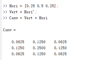
這樣有利於演演算法的進一步加速。
第二、前面講的grain_extract模式的計算是in[c] - layer[c] + 0.5f; 但是注意,正在的資料應該不需要加上這個0.5f,Gimp加上這個只是為了最終顯示的這個結果方便,不然這個計算結果很多是小於0的,就直接弄成黑色了。
第三、還是前面那個模糊,我們要特別注意在每次迭代的時候,雖然折積核是一樣的,但是隨著層數的增加,取樣的位置在越來越遠離中心點,我們用下面一副圖說明這個問題:
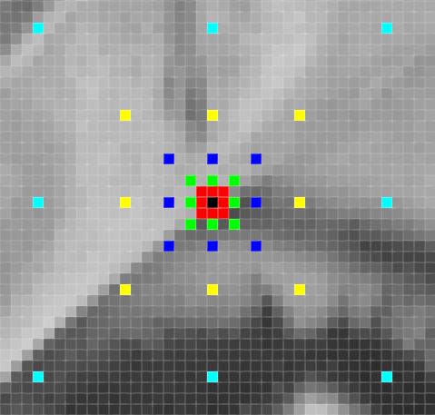
中線點是黑色的那個點,每次都參與折積,紅色的8個點是半徑為1是的取樣位置,綠色的8個點是半徑為2時的位置,藍色的為半徑為4時的取樣位置,黃色的是半徑為8時的結果給,青色的是半徑為16時的取樣位置。注意,每次的取樣圖也是不一樣的,這種也叫做Dilated convolution。
第四:和傳統的小波分解獲得的梯級結果不同(如下圖所示), GIMP這個考慮到了圖層的一些顯示方便,以及實際的可操作性,其生產的每層結果大小都是和原圖一樣的,而這個操作也是上述模糊為什麼每次的半徑都要擴大一倍的意思,因為原本是需要每層的大小都是上一層的一半,然後在執行半徑為1的模糊,現在圖層大小不變,因此就擴充套件取樣點的位置,而不改變取樣點的數量,這也是GIMP這個小波的分解的精髓所在。
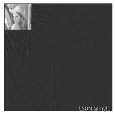
我們可以在網路中找到一些使用該外掛進行影象增強處理的例子,比如在https://patdavid.net/2011/12/getting-around-in-gimp-skin-retouching/這個連結中,提供了一些Skin Retouching的操作過程和結果,有興趣的朋友可以自行試驗下。
