如何用WebGPU流暢渲染百萬級2D物體?
大家好~本文使用WebGPU和光線追蹤演演算法,從0開始實現和逐步優化Demo,展示了從渲染500個2D物體都吃力到流暢渲染4百萬個2D物體的優化過程和思路
需求
我們對Demo提出下面的要求:
- 渲染1百萬個以上的2D物體時達到30FPS以上
暫時只渲染一種2D物體:圓環 - 記憶體佔用小
- 剔除被遮擋的物體
- 放大物體時無鋸齒,達到向量渲染的效果
成果
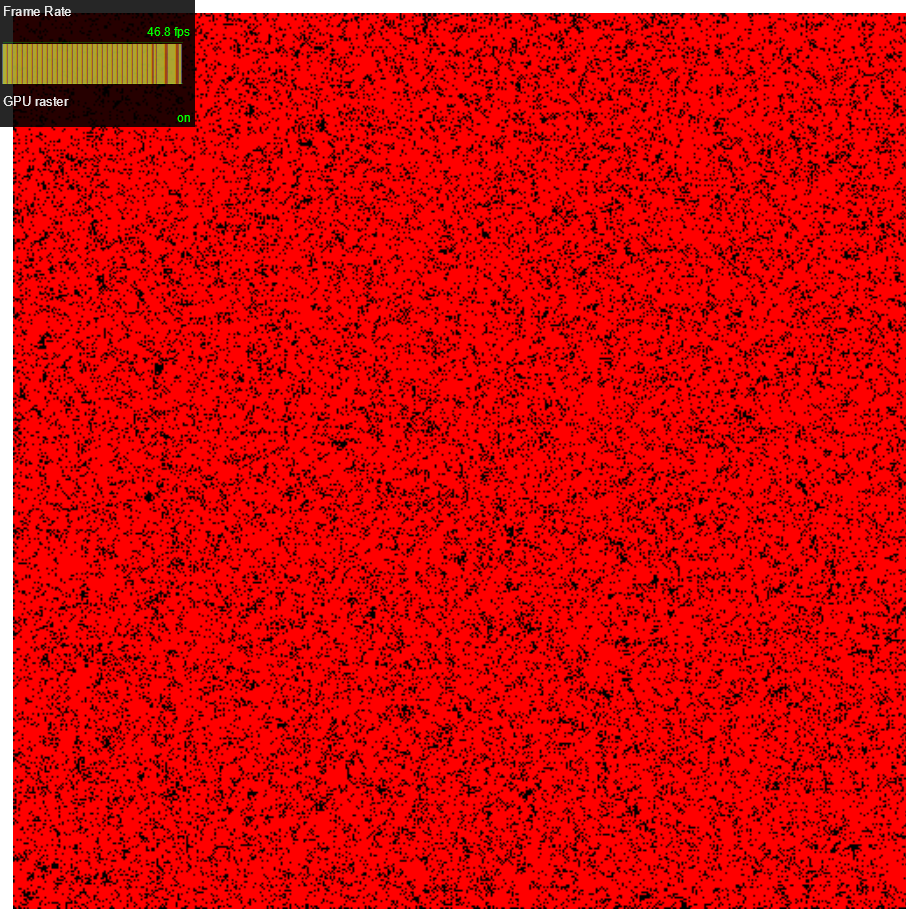
我們最終能夠流暢渲染4百萬個圓環
效能指標:
- 45 FPS左右,也就是每幀花費21毫秒
- 記憶體佔用211MB
下面讓我們從0開始,介紹實現和優化的步驟:
1、選擇渲染的演演算法
思考如何實現與渲染相關的需求
現在,我們來回顧下與渲染相關的需求,從而確定渲染演演算法:
放大物體時無鋸齒,達到向量渲染的效果
要實現該需求,可以用引數化的方法來表示物體,如用圓心座標、半徑、圓環寬度 來表示一個圓環;
然後可以根據下面的公式判斷一個點是否在圓環上:
let distanceSquare = Math.pow((點-圓心座標), 2)

let isPointInRing =  distanceSquare >= Math.pow(半徑, 2) && distanceSquare <= Math.pow(半徑 + 圓環寬度, 2)
因為圓環是2D的,是直接繪製在螢幕上的,所以這裡的一個點就是螢幕上的一個畫素
從上面的分析可知,通過「如果一個畫素在圓環上則渲染」的邏輯,就可以實現需求
剔除被遮擋的物體
要實現該需求,首先圓環加上「層」的資料;
然後遍歷所有圓環,判斷畫素在哪些圓環上;
最後取出最大「層」的圓環,將它的顏色作為畫素的顏色
選擇渲染的演演算法
有兩種渲染演演算法可選擇:光柵化渲染、光追渲染
根據我們之前對渲染需求的思考,我們應該選擇光追渲染作為渲染演演算法
典型的光追渲染會依次執行下面兩個pass:
1、光追pass
從相機向每個畫素髮射射線,經過多次射線彈射,計算每個畫素的顏色
2、螢幕pass
將螢幕光柵化,渲染每個畫素的顏色
其中光追pass是在CS(計算著色器)中進行,螢幕pass是在VS(頂點著色器)和FS(片元著色器)中進行
因為這裡是2D物體,所以需要對光追演演算法做一些簡化:
射線不需要彈射,因為不需要計算間接光照;
因為物體直接就在螢幕上,所以不需要計算射線與物體相交,而是按照引數化公式計算畫素是否在2D物體上
2、實現記憶體需求
現在來考慮如何實現「記憶體佔用小」的需求
這裡只考慮CPU端記憶體,它主要存放了場景資料,包括圓環的transform、geometry、material的資料
我們使用ECS架構,將物體建模為gameObject+components
這裡的components具體就是transform、geometry、material這些元件
按照Data Oriented的思想,每種元件就是一個ArrayBuffer,連續地存放元件資料(如transform buffer連續地存放圓環的localPositionX, localPostionY, layer(層)資料)
component為對應buffer中資料的索引
通過ECS的設計,我們就將場景資料都放在buffer中了。在初始化時,只根據最大的元件數量,建立一次對應的元件buffer。這樣就實現了記憶體佔用最小的目標
3、渲染1個圓環
現在來渲染出一個圓環,也不考慮剔除
我們依次實現下面兩個pass:
光追pass
我們需要傳入下面的場景資料到CS中,CS中對應的資料結構如下:
struct AccelerationStructure {
  worldMin : vec2<f32>,
  worldMax : vec2<f32>,

  instanceIndex: f32,
  pad_0: f32,
  pad_1: f32,
  pad_2: f32,
}

struct Instance {
  geometryIndex: f32,
  materialIndex: f32,

  localPosition: vec2<f32>,
}


struct Geometry {
  c: vec2<f32>,
  w: f32,
  r: f32,
}

struct Material {
  color: vec3<f32>,
  pad_0: f32,
}

 struct AccelerationStructures {
  accelerationStructures : array<AccelerationStructure>,
}

 struct Instances {
  instances :  array<Instance>,
}

 struct Geometrys {
  geometrys :  array<Geometry>,
}

 struct Materials {
  materials :  array<Material>,
}

 struct Pixels {
  pixels : array<vec4<f32>>
}

 struct ScreenDimension {
  resolution : vec2<f32>
}

@binding(0) @group(0) var<storage, read> sceneAccelerationStructure :  AccelerationStructures;
@binding(1) @group(0) var<storage, read> sceneInstanceData :  Instances;
@binding(2) @group(0) var<storage, read> sceneGeometryData :  Geometrys;
@binding(3) @group(0) var<storage, read> sceneMaterialData :  Materials;

@binding(4) @group(0) var<storage, read_write> pixelBuffer :  Pixels;

@binding(5) @group(0) var<uniform> screenDimension : ScreenDimension;
struct中的pad用於對齊
sceneAccelerationStructure包含圓環的包圍盒資料,作為加速相交檢測的加速結構。其中worldMin、worldMax為世界座標系中的min、max
sceneInstanceData、sceneGeometryData、sceneMaterialData為場景中所有的元件資料(sceneInstanceData為Transform資料)
instanceIndex, geometryIndex, materialIndex為對應元件資料的索引
pixelBuffer是光追pass的輸出,用來存放畫素顏色
screenDimension存放畫布的width、height
這裡為了簡單,沒有傳相機資料
在執行CS時,啟動畫布的width*height個work groups,從而讓每個畫素對應一個work group,並行執行每個畫素
相關程式碼為:
	const passEncoder = commandEncoder.beginComputePass();
	...
	passEncoder.dispatchWorkgroups(width, height);
下面我們來看下CS中計算每個畫素顏色的相關程式碼:
struct RayPayload {
   radiance: vec3<f32>,
}

struct Ray {
   target: vec2<f32>,
}

struct RingIntersect {
  isHit: bool,
  instanceIndex: f32,
}


fn _isIntersectWithAABB2D(ray: Ray, aabb: AABB2D) -> bool {
	var target = ray.target;
	var min = aabb.min;
	var max = aabb.max;

	return target.x > min.x && target.x < max.x && target.y > min.y && target.y < max.y;
}


fn _isIntersectWithRing(ray: Ray, geometry: Geometry) -> bool {
	var target = ray.target;

	var c = geometry.c;
	var w = geometry.w;
	var r = geometry.r;

	var distanceSquare = pow(target.x - c.x, 2.0) + pow(target.y - c.y, 2.0);

	return distanceSquare >= pow(r, 2) && distanceSquare <= pow(r + w, 2);
}


fn _intersectScene(ray: Ray) -> RingIntersect {
	var intersectResult: RingIntersect;

	intersectResult.isHit = false;

	var as: AccelerationStructure;

	//遍歷所有的圓環,判斷點在哪個圓環上
	for (var i: u32 = 0u; i < arrayLength(& sceneAccelerationStructure.accelerationStructures); i = i + 1u) {
		as = sceneAccelerationStructure.accelerationStructures[i];

		if (_isIntersectWithAABB2D(ray, AABB2D(as.worldMin, as.worldMax))) {
			var instance: Instance = sceneInstanceData.instances[u32(as.instanceIndex)];
			var geometryIndex = u32(instance.geometryIndex);


			var geometry: Geometry = sceneGeometryData.geometrys[geometryIndex];

			if (_isIntersectWithRing(ray, geometry)) {
					//這裡沒考慮剔除被遮擋的物體,只是直接取與第一個相交圓環的結果

					intersectResult.isHit = true;
					intersectResult.instanceIndex = as.instanceIndex;

					break;
			}
		}
	}

	return intersectResult;
}

//這裡使用了WGSL的pointer type,相當於GLSL的inout,實現對payload的參照修改
fn _handleRayHit(payload: ptr<function,RayPayload>, ray: Ray, intersectResult: RingIntersect)->bool {
  var instance: Instance = sceneInstanceData.instances[u32(intersectResult.instanceIndex)];
  var materialIndex = u32(instance.materialIndex);

  var material:Material = sceneMaterialData.materials[materialIndex];

  (*payload).radiance = material.color;

  return false;
}

fn _handleRayMiss(payload: ptr<function,RayPayload>)->bool {
  (*payload).radiance = vec3<f32>(0.0, 0.0, 0.0);

  return false;
}


fn _traceRay(ray: Ray, payload: ptr<function,RayPayload>)->bool {
  var intersectResult: RingIntersect = _intersectScene(ray);

  if (intersectResult.isHit) {
    return _handleRayHit(payload, ray, intersectResult);
  }

  return _handleRayMiss(payload);
}

@compute @workgroup_size(1, 1, 1)
fn main(@builtin(global_invocation_id) GlobalInvocationID: vec3<u32>) {
  var ipos = vec2<u32>(GlobalInvocationID.x, GlobalInvocationID.y);

  var resolution = vec2<f32>(screenDimension.resolution);

  var pixelColor = vec3<f32>(0.0, 0.0, 0.0);

  //取畫素中心為畫素座標
  var sampledPixel = vec2<f32>(f32(ipos.x) + 0.5, f32(ipos.y) + 0.5);
  //獲得螢幕座標系中的畫素座標
  var uv = (sampledPixel / resolution) * 2.0 - 1.0;


  //畫素座標就是點座標(因為沒有使用相機,所以它就相當於在世界座標系中)
  var target = uv;
  /* 如果使用了相機的話,需要將其轉換到世界座標系中:
  var target = 相機的檢視矩陣的逆矩陣 * 相機的投影矩陣的逆矩陣 * uv;
  */

  var payload: RayPayload;
  payload.radiance = vec3<f32>(0.0, 0.0, 0.0);


  var _isContinueBounce = _traceRay(Ray(target.xy), & payload);


  pixelColor = payload.radiance;

  var pixelIndex = ipos.y * u32(resolution.x) + ipos.x;
  pixelBuffer.pixels[pixelIndex] = vec4<f32>(pixelColor, 1.0);
}
看程式碼應該就能理解了吧,就不說明了
螢幕pass
在VS中,使用一個大的三角形包含整個螢幕,程式碼為:
struct VertexOutput {
	@builtin(position) Position: vec4 < f32 >,
	@location(0) uv: vec2 < f32 >,
}

@vertex
fn main(
	@builtin(vertex_index) VertexIndex: u32
) -> VertexOutput {
	var output: VertexOutput;
	output.uv = vec2<f32>(f32((VertexIndex << 1) & 2), f32(VertexIndex & 2));
	output.Position = vec4<f32>(output.uv * 2.0 - 1.0, 0.0, 1.0);

	return output;
}
在FS中,讀取光追pass輸出的畫素顏色,程式碼為:
struct Pixels {
	pixels: array<vec4<f32>>
}

struct ScreenDimension {
	resolution: vec2<f32>
}


@binding(0) @group(0) var<storage, read_write > pixelBuffer : Pixels;
@binding(1) @group(0) var<uniform>screenDimension : ScreenDimension;

@fragment
fn main(
  @location(0) uv: vec2<f32>
) -> @location(0) vec4 < f32 > {
	var resolution = vec2<f32>(screenDimension.resolution);

	var bufferCoord = vec2<u32>(floor(uv * resolution));
	var pixelIndex = bufferCoord.y * u32(resolution.x) + bufferCoord.x;

	var pixelColor = pixelBuffer.pixels[pixelIndex].rgb;

	return vec4<f32>(pixelColor, 1.0);
}
4、測試渲染極限
現在我們來渲染500個圓環,測試下FPS
渲染結果如下圖所示:

發現效能問題:現在FPS為45,低於60!
我們來分析下CS中的效能熱點:
首先在粗粒度上確定熱點範圍
我們將_intersectScene函數中的for迴圈註釋掉,再次執行Demo,FPS提升為60
這說明_intersectScene的for迴圈這塊是效能熱點
我們來分析這塊程式碼:
現在每次遍歷都會執行arrayLength函數,而它的效能較差。因此將其提出來只執行一次
程式碼修改為:
  var length = arrayLength(&sceneAccelerationStructure.accelerationStructures);
  for (var i : u32 = 0u; i < length; i = i + 1u) {
取消for迴圈的註釋,再次執行Demo,FPS提升為60
現在for迴圈會遍歷每個圓環,應該要引入BVH來減少遍歷次數。不過因為BVH實現起來比較複雜,所以不忙引入,而是先考慮容易實現的優化
5、嘗試設定workgroup_size
目前work group的size設為(1,1,1),沒有啟用區域性單位
我們介紹下work group和它的區域性單位的概念:

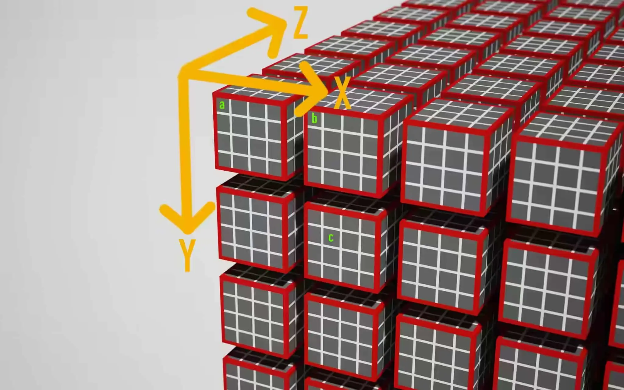
如上圖所示,一個紅色的立方體表示一個work group(通過"passEncoder.dispatchWorkgroups(x1,y1,z1)"來指定啟動(x1乘以y1乘以z1)個work group); 紅色立方體裡面又包含多個小的立方體,每個表示一個區域性單位(通過"@workgroup_size(x2,y2,z2)"來指定啟動一個work group中(x2乘以y2乘以z2)個區域性單位)
那麼總共就有(x1乘以y1乘以z1乘以x2乘以y2乘以z2)次著色器呼叫,它們都是並行執行的
既然都是並行執行,那麼只需要用work group就好了,為什麼要用到work group內的區域性單位呢?
這是因為下面兩個原因:
1、提供共用變數
同一個work group的區域性單位之間可以共用變數
如實現影象降噪時,需要獲得一個畫素周圍33範圍的畫素來一起計算,它們需要共用一些資料。因此可指定為@workgroup_size(3,3,1)
2、提高效能
因為GPU中有多個計算單位,每個計算單位可以看成是一個work group;每個計算單位中一般可以同時執行88個執行緒。
如果將work group size設為1,則只使用了計算單位中的1個執行緒而不是64個執行緒
所以,一般將work group size設為64(如(64,1,1)或者(8,8,1)),則可以使用計算單位的64個執行緒,而減少了所需的計算單位數量(變為原來的1/64),這樣就提高了效能
這也是為什麼我們要使用WebGPU而不是WebGL來實現本Demo:因為只有WebGPU才有CS,而CS可以充分利用計算單位中的執行緒,提高效能
啟用區域性單位
現在我們將work group數量減少為原來的1/64:
	let workgroup_size = {
		width: 8,
		height: 8
	}

	const passEncoder = commandEncoder.beginComputePass();
	...
	passEncoder.dispatchWorkgroups(Math.ceil(width / workgroup_size.width), Math.ceil(height / workgroup_size.height));
同時將work group的size設為(8,8,1):
@compute @workgroup_size(8, 8, 1)
但是執行Demo後,發現FPS不僅沒有增加,反而更低了!
這是為什麼呢?
通過學習下面的資料:
Optimizing GPU occupancy and resource usage with large thread groups
我們知道了一個計算單位中只有64KB的記憶體用於儲存(我們只用到了64KB的VGPRs (Vector General-Purpose Registers)),並且由於一個計算單位會並行執行兩個執行緒組,所以每個執行緒組只有32KB的記憶體大小。
然而在_intersectScene的for迴圈中遍歷了所有的圓環。這意味著會將所有圓環的資料都載入到計算單位的記憶體中,從而超過了32KB的大小!
這導致了計算單位只能使用1個執行緒組,並且該執行緒組只能使用1個而不是所有的執行緒!
所以不僅相當於沒啟用區域性單位,反而可能因為試圖啟用區域性單位而造成的同步開銷,導致FPS不升反降!
結論
綜上分析,我們需要引入BVH,大幅減少for迴圈中需要遍歷的資料,使其小於32KB,從而能夠將其載入到計算單位的記憶體中;
然後我們再啟用8*8的區域性單位!
6、實現BVH
BVH是一個用於空間劃分的樹,相關介紹可參考:
場景管理方法之BVH介紹
GAMES101-現代計算機圖學入門-閆令琪
我們需要在CPU端構造BVH樹,將其傳入到CS;然後在CS->_intersectScene函數中遍歷BVH
6.1、實現構造BVH
構造BVH樹
我們在CPU端使用最簡單暴力的Middle方法構造BVH樹,步驟如下:
1、計算所有圓環的包圍盒AABB
2、構造根節點,以所有AABB形成的整體AABB為該節點的包圍盒
3、從x軸方向,按照AABB的中心點位置排序所有的AABB
4、以中間的AABB為分界線分割,形成兩個子節點,每個子節點以其包含的所有AABB形成的整體AABB為該子節點的包圍盒
5、遞迴地構造這兩個子節點,並且交替地從y軸方向開始(即x軸->y軸->x軸。。。。。。交替)排序該節點包含的所有AABB和分割。。。。。。直到節點包含的AABB個數<=5或達到最大深度時結束遞迴
構造加速結構
因為CS中只能用陣列,所以需要將BVH樹拍平成陣列,作為加速結構傳送到CS
我們將加速結構設計為兩層:TopLevel和BottomLevel
BottomLevel的資料型別如下:
type worldMinX = number
type worldMinY = number
type worldMaxX = number
type worldMaxY = number

type instanceIndex = number

type bottomLevel = Array<[worldMinX, worldMinY, worldMaxX, worldMaxY, instanceIndex]>
BottomLevel用來儲存所有圓環對應的包圍盒、instanceIndex
TopLevel的資料型別如下:
type wholeWorldMinX = number
type wholeWorldMinY = number
type wholeWorldMaxX = number
type wholeWorldMaxY = number

type leafInstanceOffset = number
type leafInstanceCount = number
type child1Index = number
type child2Index = number

type topLevel = Array<[
	wholeWorldMinX, wholeWorldMinY, wholeWorldMaxX, wholeWorldMaxY,
	leafInstanceOffset,
	leafInstanceCount,
	child1Index,
	child2Index
]>
TopLevel用來儲存BVH節點的包圍盒、節點包含的AABB在BottomLevel陣列中的索引(如果該節點不是葉節點,則leafInstanceCount=0)、子節點在topLevel陣列中的索引
然後將加速結構傳到CS中,CS中對應資料結構如下:
struct TopLevel {
  worldMin : vec2<f32>,
  worldMax : vec2<f32>,

  leafInstanceOffset: f32,
  leafInstanceCount: f32,
  child1Index: f32,
  child2Index: f32
}

struct BottomLevel {
  worldMin : vec2<f32>,
  worldMax : vec2<f32>,

  instanceIndex: f32,
  pad_0: f32,
  pad_1: f32,
  pad_2: f32,
}

 struct TopLevels {
  topLevels : array<TopLevel>,
}

 struct BottomLevels {
  bottomLevels : array<BottomLevel>,
}

@binding(0) @group(0) var<storage> topLevel : TopLevels;
@binding(1) @group(0) var<storage> bottomLevel : BottomLevels;
6.2、CPU端實現遍歷BVH
為了方便測試,我們先在CPU端實現遍歷BVH;解決所有bug後,再移植到CS中
可以分別用遞迴和迭代來實現
考慮到WGSL不支援遞迴函數,所以我們只用迭代來實現
相關程式碼如下:
type traverseResult = {
	isHit: boolean,
	instanceIndex: instanceIndex | null
}

let _isPointIntersectWithAABB = (
	point,
	wholeWorldMinX, wholeWorldMinY, wholeWorldMaxX, wholeWorldMaxY,
) => {
	return point[0] > wholeWorldMinX && point[0] < wholeWorldMaxX && point[1] > wholeWorldMinY && point[1] < wholeWorldMaxY
}

let _isPointIntersectWithTopLevelNode = (point, node: topLevelNodeData) => {
	let [
		wholeWorldMinX, wholeWorldMinY, wholeWorldMaxX, wholeWorldMaxY,
		leafInstanceOffset,
		leafInstanceCount,
		child1Index,
		child2Index
	] = node

	return _isPointIntersectWithAABB(
		point,
		wholeWorldMinX, wholeWorldMinY, wholeWorldMaxX, wholeWorldMaxY,
	)
}

let _isLeafNode = (node: topLevelNodeData) => {
	let leafInstanceCountOffset = 5

	return node[leafInstanceCountOffset] !== 0
}

let _handleIntersectWithLeafNode = (intersectResult, isIntersectWithInstance, point, node: topLevelNodeData, bottomLevelArr: bottomLevelArr) => {
	let [
		wholeWorldMinX, wholeWorldMinY, wholeWorldMaxX, wholeWorldMaxY,
		leafInstanceOffset,
		leafInstanceCount,
		child1Index,
		child2Index
	] = node

	while (leafInstanceCount > 0) {
		let [worldMinX, worldMinY, worldMaxX, worldMaxY, instanceIndex] = bottomLevelArr[leafInstanceOffset]

		if (_isPointIntersectWithAABB(
			point,
			worldMinX, worldMinY, worldMaxX, worldMaxY
		)) {
			if (isIntersectWithInstance(point, instanceIndex)) {
				intersectResult.isHit = true
				intersectResult.instanceIndex = instanceIndex

				break;
			}
		}

		leafInstanceCount -= 1
		leafInstanceOffset += 1
	}
}

let _hasChild = (node, childIndexOffset) => {
	return node[childIndexOffset] !== 0
}

export let traverse = (isIntersectWithInstance, point, topLevelArr: topLevelArr, bottomLevelArr: bottomLevelArr): traverseResult => {
	let rootNode = topLevelArr[0]

	let child1IndexOffset = 6
	let child2IndexOffset = 7

	let stackContainer = [rootNode]
	let stackSize = 1

	let intersectResult = {
		isHit: false,
		instanceIndex: null
	}

	while (stackSize > 0) {
		let currentNode = stackContainer[stackSize - 1]

		stackSize -= 1

		if (_isPointIntersectWithTopLevelNode(point, currentNode)) {
			if (_isLeafNode(currentNode)) {
				_handleIntersectWithLeafNode(intersectResult, isIntersectWithInstance, point, currentNode, bottomLevelArr)

				if (intersectResult.isHit) {
					break
				}
			}
			else {
				if (_hasChild(currentNode, child1IndexOffset)) {
					stackContainer[stackSize] = topLevelArr[currentNode[child1IndexOffset]]
					stackSize += 1
				}
				if (_hasChild(currentNode, child2IndexOffset)) {
					stackContainer[stackSize] = topLevelArr[currentNode[child2IndexOffset]]
					stackSize += 1
				}
			}
		}
	}

	return intersectResult
}
這裡用了棧(stackContainer)來儲存需要遍歷的節點
本來我們可以直接通過stackContainer.push方法將節點push到棧中,但考慮到WGSL的陣列沒有push操作,所以這裡我們就增加了stackSize這個資料,從而能夠通過"stackContainer[stackSize] = 節點"來代替"stackContainer.push(節點)"
6.3、GPU端實現遍歷BVH
CPU端測試通過後,我們將其移植到CS中
這裡值得注意的是因為WGSL建立陣列時必須定義大小,所以棧的大小必須預先確定且為常數
棧的大小其實就是BVH樹的最大深度,我們可以先暫時指定為20
相關程式碼如下:
fn _intersectScene(ray: Ray)->RingIntersect {
const MAX_DEPTH = 20;

var stackContainer:array<TopLevel, MAX_DEPTH>;

...
}
7、測試渲染極限
現在我們將圓環數量增加200倍,渲染500*200=10萬個圓環,測試下FPS
我們將圓環的半徑和圓環寬度縮小為1/10,這樣方便顯示
渲染結果如下圖所示:

FPS沒有變化
結論
通過引入BVH,渲染效能提高了200倍
8、設定workgroup_size
因為引入了BVH,需要遍歷的節點數大大減少了,所以減少了視訊記憶體佔用
現在再次啟用區域性單位:
我們將work group減少為原來的1/64,將work group的size設為(8,8,1):
執行Demo後,發現FPS變為60了
理論上可以提高64倍的渲染速度
所以我們將圓環數量增加40倍,渲染10萬*40=4百萬個圓環,測試下FPS
結果FPS跟之前10萬個時一樣
結論
通過啟用區域性單位,渲染效能提高了40倍
9、測試記憶體佔用
通過Chrome dev tool->Memory->Take heap snapshot,可以看到包含4百萬個圓環的場景在CPU端只佔用了211MB左右的記憶體,說明記憶體佔用確實小
10、使用LBVH演演算法來構造BVH
現在當圓環數量為4百萬個時,CPU端構造BVH需要花費100秒以上的時間!
因此,我們保持「構造加速結構」的程式碼不變,修改「構造BVH樹」的演演算法為LBVH演演算法
它的步驟如下:
1、計算所有圓環的包圍盒AABB
2、構造根節點,以所有AABB形成的AABB為該節點的包圍盒
3、根據根節點的包圍盒,在x、y軸方向上將其1024等分,根據AABB的中心點在哪個區域而計算出AABB在x、y軸方向上的格子座標
4、將格子座標轉換為Morton Code
5、根據Morton Code將所有的AABB排序
6、對於該有序Morton Code陣列,我們利用二分查詢出第一個不同的bit位(也即是從0變為1的index),此時我們即可將最高位為0的所有BVs歸入此node(此時是root節點)的左子樹,最高位為1的所有BVs歸入右子樹;同理,我們對左右子樹按照下一個bit位來遞迴的處理,直到遞迴的處理完全部bit位,LBVH即可建立完畢
最後一步如下圖所示:

結論
通過改為LBVH演演算法,構造時間降低為10秒左右,效能提高了10倍
之所以LBVH演演算法更快,是因為只排序了一次!
11、實現剔除
之前分析過剔除的實現思路:
首先圓環加上「層」的資料;
然後遍歷所有圓環,判斷畫素在哪些圓環上;
最後取出最大「層」的圓環,將它的顏色作為畫素的顏色
因此,可以在圓環的transform元件資料中增加layer資料(從1開始的正整數),用來表示「層」;
然後在構造加速結構BottomLevel時,讀取transform元件中的layer資料,將其儲存到BottomLevel資料中;
最後修改CS程式碼,在遍歷BVH->檢測到畫素在圓環上時比較layer,並且不再停止遍歷,而是繼續遍歷棧的其它節點;在遍歷棧的其它節點時,如果找到了畫素在其上的圓環,也不再停止
實現剔除後,執行Demo渲染1百萬個圓環時FPS都才15(之前是4百萬個 45 FPS),渲染效能估計降低了10倍
12、改進遍歷BVH
我們從下面幾個方面對剔除進行優化
traverse order優化
現在如果找到了畫素在其上的圓環,會繼續遍歷其它節點。
我們需要減少遍歷的節點數量
我們可以在構造BVH樹時,為每個節點增加maxLayer資料,它為該節點包含的所有的圓環中最大的層;
然後在遍歷BVH時:
檢測到畫素在圓環上時,將圓環的layer記錄到相交結果intersectResult中;
在遍歷棧中的節點的while迴圈中,如果該節點的maxLayer <= intersectResult.layer,則說明該節點包含的所有圓環都被遮擋了,直接continue,跳過;
另外,在遍歷葉節點的所有圓環時,如果畫素所在的圓環的layer==該節點的maxLayer,則說明已經找到了葉節點包含的所有圓環中的最大層的圓環,則break,停止搜尋該葉節點包含的其它圓環。
通過上面的優化,可以大幅降低遍歷的節點數量
合併資料
因為BVH樹的節點需要儲存maxLayer資料,而這個資料實際上是儲存在TopLevel中的,對應到CS中的資料結構就是:
struct TopLevel {
	worldMin : vec2<f32>,
	worldMax : vec2<f32>,

	leafInstanceOffset: f32,
	leafInstanceCount: f32,
	child1Index: f32,
	child2Index: f32

	maxLayer: f32,
	pad_0: f32,
	pad_1: f32,
	pad_2: f32,
}
我們可以看到,因為增加了maxLayer,需要增加3個pad資料來對齊,這樣浪費了視訊記憶體
而佔用儘可能少的視訊記憶體是非常重要的,因為經過之前的分析,我們知道一個計算單位只有32KB的視訊記憶體可用,超過的話就會導致啟用區域性單位失效!
仔細觀察後,我們發現leafInstanceCount和maxLayer只需要佔用<32位元的位元組數
我們可以讓這兩個資料各佔16位元,其中leafInstanceCount在高位,maxLayer在低位;然後將其合成一個32位元f32
從而TopLevel修改為:
struct TopLevel {
	worldMin : vec2<f32>,
	worldMax : vec2<f32>,

	leafInstanceOffset: f32,
	leafInstanceCountAndMaxLayer: f32,
	child1Index: f32,
	child2Index: f32
}
這樣就消除了pad資料,減少了視訊記憶體佔用
但是當渲染的圓環數量超過1百萬個時,會出現「從leafInstanceCountAndMaxLayer中取出的maxLayer為0(應該>=1)」的bug!
這是因為leafInstanceCount(葉節點的圓環個數)過大,佔用了超出了16位元的位元組數,從而影響到maxLayer的值!
所以我們重新分配,讓leafInstanceCount佔24位元,maxLayer佔8位元,則解決了bug
注:理論上16位元的leafInstanceCount可以最大為65535,但實際上我發現當leafInstanceCount>1000時,就出現了超過16位元的情況!我估計是WGLSL可能佔用了f32型別的資料的最高几位,導致leafInstanceCount實際可用位數<16位元
13、測試渲染極限
現在我們將圓環數量恢復為4百萬個圓環,FPS又恢復為45左右
當我們嘗試渲染5百萬個圓環時,遇到了「我們BottomLevel Buffer資料超出了Storage Buffer的最大限制:128MB」的問題
關於這個限制,WebGPU官方有相關的討論issue:
Limit for the maximum buffer size
繞過該限制的可能方案是將其拆成多個Storage Buffer
結論
通過traverse order優化,渲染效能提高了10倍左右
當我們嘗試渲染5百萬個圓環時,遇到了超出Storage Buffer最大大小的限制
總結
感謝大家的學習~
在本文中,我們先提出了需求;然後按照需求來設計和選擇演演算法;然後實現最簡單的版本;接著不斷優化,直到達到Storage Buffer的最大大小限制為止
我們的優化的成果為:
- 通過引入BVH,渲染效能提高了200倍
- 通過啟用區域性單位,渲染效能提高了40倍
- 通過改為LBVH演演算法,效能提高了10倍
- 通過traverse order優化,使得剔除的效能提高了10倍左右
目前我們最多渲染4百萬個圓環,因為再多就會超出Storage Buffer最大大小的限制
後續的改進方向
後面我們希望能夠渲染千萬級2D物體,可以從下面的方向改進:
- 將加速結構拆成多個Storage Buffer
- 優化構造BVH,使葉節點包含的圓環數量儘量少,且節點的包圍盒儘量不重疊,這樣才能提高遍歷BVH的效能
可考慮使用HLBVH演演算法 - 優化遍歷BVH:考慮並行遍歷BVH、無棧的遍歷
參考Ray Tracing學習之Traversal
參考資料
OpenGL4.3 新特性: 計算著色器 Compute Shader
Bad preformance of simple ray trace compute shader
Optimizing GPU occupancy and resource usage with large thread groups
我所理解的DirectX Ray Tracing
並行構建BVH
Build LBVH on GPUs
Ray Tracing學習之Traversal
光線求交加速演演算法:邊界體積層次結構(Bounding Volume Hierarchies)3-LBVH(Linear Bounding Volume Hierarchies)
WebGPU 計算管線、計算著色器(通用計算)入門案例:2D 物理模擬

