ROS機械臂 Movelt 學習筆記2 | Move Group 介面 C++
Movelt為使用者提供了一個最通用且簡單的介面 MoveGroupInterface 類,這個介面提供了很多控制機器人的常用基本操作,如:
- 設定機械臂的位姿
- 進行運動規劃
- 移動機器人本體
- 將物品新增到環境 / 從環境移除
- 將物體系結到機器人 / 從機器人解綁
這個介面通過ROS話題topic、服務service和動作action等機制與 MoveGroup 節點進行通訊。
有關ROS節點相關知識以後會介紹,參見ROS Nodes
1. 執行範例程式碼
1.1 執行過程
cd ~/ARM/ws_moveit/
source devel/setup.bash
roslaunch panda_moveit_config demo.launch
新開一個終端,在相同目錄下執行
source devel/setup.bash
roslaunch moveit_tutorials move_group_interface_tutorial.launch
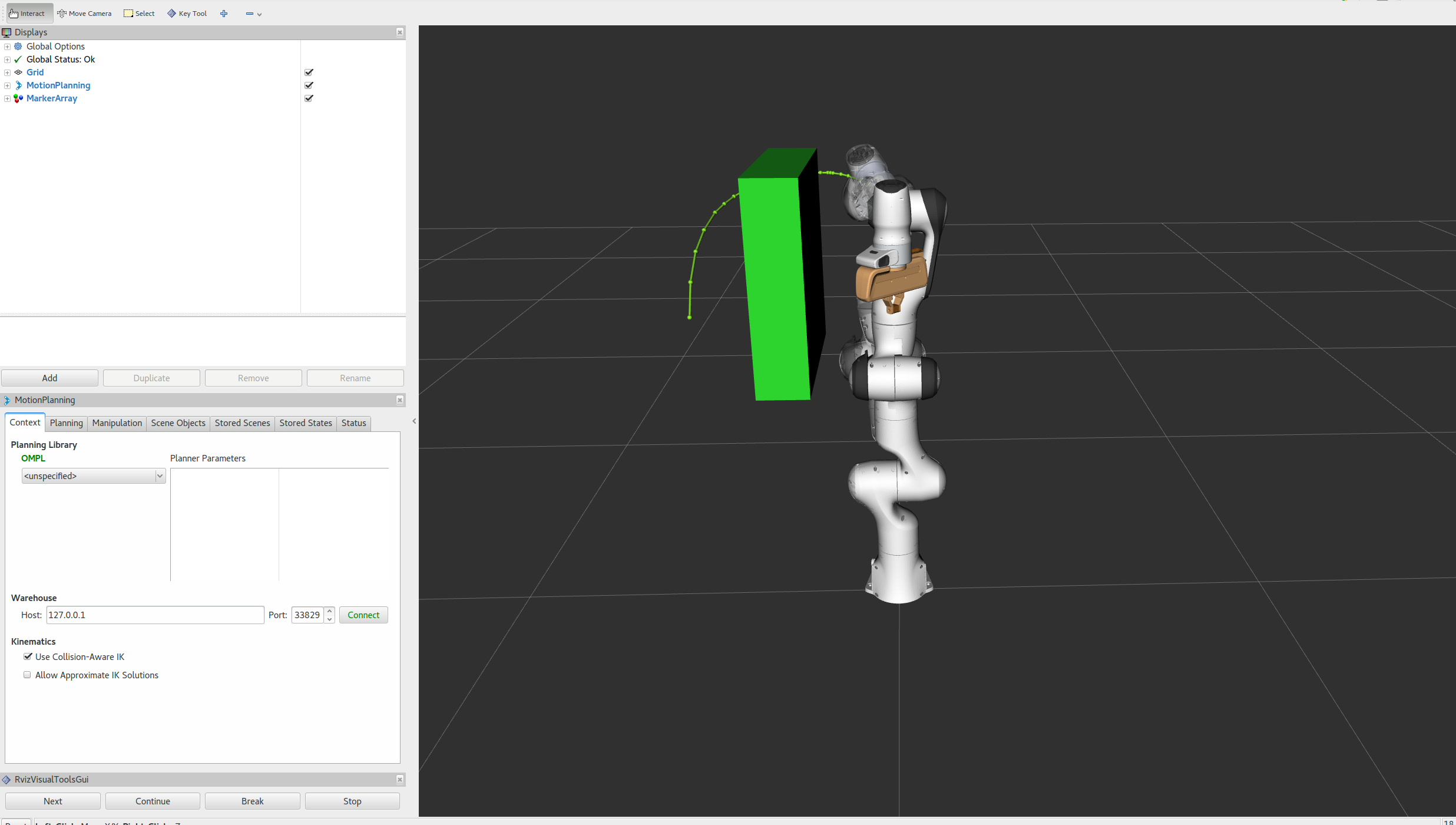
注意:例程使用 RvizVisualToolsGui 面板逐步完成演示。預設應當是直接出現的。
如果沒有,要將此面板新增到 RViz,參考基礎準備。
程式執行過程中的 rviz 如下圖所示,跟隨第二個終端裡的提示,在螢幕底部 RvizVisualToolsGui 面板中按下 Next 按鈕。
或選擇螢幕頂部工具面板 (Interact那一行) 中的Key Tool 工具,然後按鍵盤上的 N 來進行下一步。

1.2 debug 過程
1.2.1 visual_tools 缺包
在執行上面的第二個命令時,我發生報錯:
[move_group_interface_tutorial-1] process has died [pid 10609, exit code 127, cmd /home/zzrs234/ARM/ws_moveit/devel/lib/moveit_tutorials/move_group_interface_tutorial __name:=move_group_interface_tutorial __log:=/home/zzrs234/.ros/log/fe0cbdfa-08cc-11ed-8c8a-bc6ee239de01/move_group_interface_tutorial-1.log].
log file: /home/zzrs234/.ros/log/fe0cbdfa-08cc-11ed-8c8a-bc6ee239de01/move_group_interface_tutorial-1*.log
因為是 devel 包中的問題,所以,我重新編譯:
zzrs234@zzrs234:~/ARM/ws_moveit$ catkin build
發現果然有錯誤:
Could not find a package configuration file provided by
  "moveit_visual_tools" with any of the following names:

    moveit_visual_toolsConfig.cmake
    moveit_visual_tools-config.cmake
這種錯誤很經典,就是缺包,執行以下命令進行安裝:
sudo apt-get install ros-melodic-moveit-visual-tools# ubuntu18.04
再重新編譯,執行上面 1.1 的命令即可。
1.2.2 只顯示路徑而機械臂不到位
在初步執行時,發現機械臂只執行一次,留下一個綠色帶點的路徑,就又復歸原來位置,對於將物品附加到機械臂的效果體現不明顯(因為機械臂回到了原位置)。
這是因為只是規劃而不是執行,只會留下路徑。
1.3 預期效果
在RViz中,我們應該能夠看到以下效果:
-
機器人將其手臂移動到其前方的目標姿態。
-
機器人將其手臂移動到其側面的目標姿態。
-
機器人將其手臂移到一個新的目標姿態,同時保持末端執行器水平。
-
機器人沿著設定好的笛卡爾路徑(一個三角形,下、右、上+左)移動手臂。
-
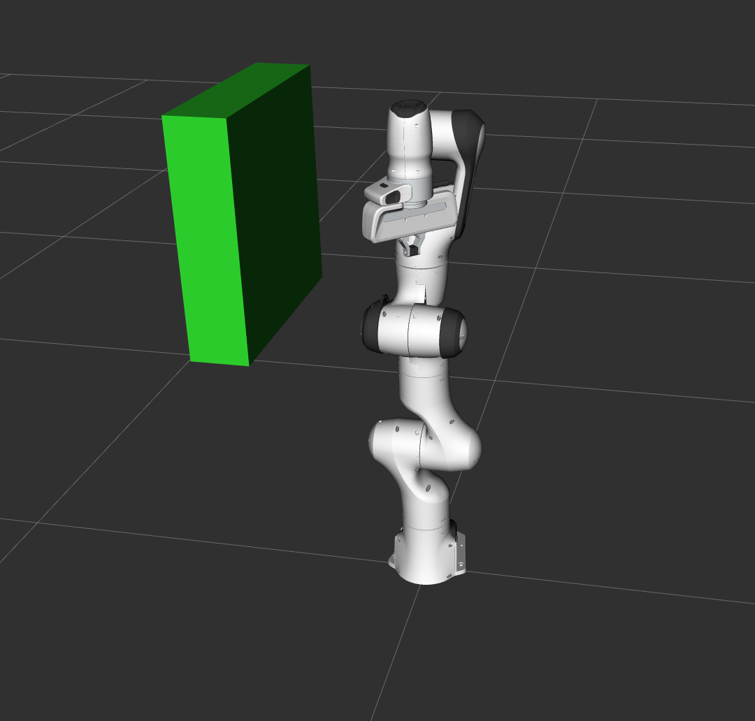
將長方體物件新增到手臂右側的環境中。

-
機器人將其手臂移動到目標位姿,越過箱子,避免與箱子碰撞。
-
該物件附加到腕部(末端爪的側面),並將其顏色將更改為紫色/橙色/綠色。
-
物體從腕部分離(其顏色將變回綠色)。
-
將箱子將從環境中刪除。
2. 程式碼分析
實現這個功能的程式碼在~/ARM/ws_moveit/src/moveit_tutorials/doc/move_group_interface/src下,Github地址為:完整程式碼地址。
下面我們一步一步分析一下 Movelt 是如何實現這些操作的。
程式碼給我的印象是,名字很複雜,但從上向下通讀並不難,邏輯很簡單,閱讀原始碼很容易知道各個函數是什麼意思。
2.1 Setup 初始化
這部分是對 Movelt 的幾個介面類的初始化。
2.1.1 MoveGroupInterface
MoveIt程式設計 是對 規劃組 planning groups 進行操作的。
//建立介面物件 PLANNING_GROUP
static const std::string PLANNING_GROUP = "panda_arm";
MoveGroupInterface類只需放入 想要控制和規劃的 planning group 的名稱 即可設定。
規劃組planning group:
是我們設定的,設定過程會在後續講解倒入機器人模型時講解。
例如 panda機械臂,在Rviz的 Planning Request 中可以看到它有 3 個 Planning Group 規劃組:
hand \ panda_arm \ panda_arm_hand
決定我們操作的機器人物件。
moveit::planning_interface::MoveGroupInterface move_group(PLANNING_GROUP);
2.1.2 PlanningSceneInterface
PlanningSceneInterface 類將被用來在 "virtual world" 場景中新增和刪除碰撞物件 :
moveit::planning_interface::PlanningSceneInterface planning_scene_interface;
2.1.3 JointModelGroup
建立 MoveGroupInterface 物件後,Planning Group 會被儲存到 JointModelGroup 物件。所以在 MoveIt 程式設計中通常會把 planning group 叫做 joint model group。
構建一個指標指向 JointModelGroup 物件,有些情況下會直接對 joint model group 進行操作。
// 獲取當前關節狀態
//呼叫 getJointModelGroup 將位置姿態 放入 joint_model_group,這個後續2.6會用。
const robot_state::JointModelGroup* joint_model_group =
    move_group.getCurrentState()->getJointModelGroup(PLANNING_GROUP);
2.2 Visualization 視覺化
MoveItVisualTools包是一個在 Rviz 中視覺化的工具包。比如:
- 物體 | 機器人 | 軌跡 | 偵錯資訊
namespace rvt = rviz_visual_tools;
moveit_visual_tools::MoveItVisualTools visual_tools("panda_link0");
visual_tools.deleteAllMarkers();
遠端控制 Remote control 是一種自省工具 (introspection tool ),可以通過RViz中的按鈕和鍵盤快捷鍵逐步完成高階功能。
visual_tools.loadRemoteControl();
RViz提供了多種型別的標記markers,用於記錄歷史軌跡和表徵資訊。在本演示中,我們將使用文字 test、圓柱體 cylinders,和球體 spheres:
Eigen::Isometry3d text_pose = Eigen::Isometry3d::Identity();
text_pose.translation().z() = 1.75;
visual_tools.publishText(text_pose, "MoveGroupInterface Demo", rvt::WHITE, rvt::XLARGE);
Eigen 參見 相關部落格
rviz 中的 markers參見:
批次釋出trigger 可以減少傳送到RViz進行視覺化的訊息數量:
visual_tools.trigger();
2.3 列印基本資訊
我們可以列印一些基本資訊到終端裡顯示出來:
-
參考系的名字
ROS_INFO_NAMED("tutorial", "Planning frame: %s", move_group.getPlanningFrame().c_str()); -
機器人的末端執行器
ROS_INFO_NAMED("tutorial", "End effector link: %s", move_group.getEndEffectorLink().c_str()); -
機器人的規劃組
ROS_INFO_NAMED("tutorial", "Available Planning Groups:");
std::copy(move_group.getJointModelGroupNames().begin(), move_group.getJointModelGroupNames().end(),
          std::ostream_iterator<std::string>(std::cout, ", "));
2.4 Start the demo
呼叫 visual_tools 的 prompt 提示函數 來開始操作:
visual_tools.prompt("Press 'next' in the RvizVisualToolsGui window to start the demo");
後續執行完一次規劃都會來這麼一句,在 RViz 中進行互動。
2.5 Planning to a Pose goal
2.5.1 設定目標末端姿態
可以為規劃組(上面指定過為 panda_arm) 指定一個末端執行器的目標位姿(就是機械爪,end-effector):
//設定目標位姿
geometry_msgs::Pose target_pose1;
target_pose1.orientation.w = 1.0;
target_pose1.position.x = 0.28;
target_pose1.position.y = -0.2;
target_pose1.position.z = 0.5;
move_group.setPoseTarget(target_pose1);
接下來,就可以呼叫規劃器來計算、規劃並將其視覺化。請注意,我們只是在規劃,而不是呼叫 move_group 實際移動機器人。
//呼叫規劃器進行規劃

//建立規劃器
moveit::planning_interface::MoveGroupInterface::Plan my_plan;
//成功標誌位
bool success = (move_group.plan(my_plan) == moveit::planning_interface::MoveItErrorCode::SUCCESS);
//輸出
ROS_INFO_NAMED("tutorial", "Visualizing plan 1 (pose goal) %s", success ? "" : "FAILED");
2.5.2 規劃視覺化
還記得上面 2.2 中的 markers 嗎?
我們還可以在RViz 中將規劃軌跡用 markers 展示出來:
//視覺化規劃軌跡

ROS_INFO_NAMED("tutorial", "Visualizing plan 1 as trajectory line");
visual_tools.publishAxisLabeled(target_pose1, "pose1");
//markers建立
visual_tools.publishText(text_pose, "Pose Goal", rvt::WHITE, rvt::XLARGE);
//畫線
visual_tools.publishTrajectoryLine(my_plan.trajectory_, joint_model_group);
visual_tools.trigger();
//完成一次規劃,與RViz 介面進行互動,使其點選 next 再繼續執行。
visual_tools.prompt("Press 'next' in the RvizVisualToolsGui window to continue the demo");
2.5.3 移動到目標姿態
移動到姿勢目標與上述步驟類似,只是我們現在使用move()函數。請注意,之前設定的目標姿勢仍處於活動狀態,因此機器人將嘗試移動到該目標。
本教學中不會使用該函數,因為它是一個阻塞函數,需要 控制器controller(也就是真實硬體) 處於活動狀態並報告軌跡執行成功。
/* Uncomment below line when working with a real robot */
/* move_group.move(); */

//這裡註釋掉因為是模擬,沒有在硬體上執行,呼叫的話會阻塞。
2.6 Planning to a joint-space goal
除了上面提到的 Pose Goal,還有 Joint-space Goal ,這種方式通過在關節空間定義一個目標關節狀態的方式進行控制。
2.6.1 設定目標關節姿態
-
首先,建立一個指向 RobotState 的指標 current_state 。RobotState 記錄了 Planning Group 中各個關節的 位置 / 速度 / 加速度資料
moveit::core::RobotStatePtr current_state = move_group.getCurrentState(); -
接下來,獲取當前狀態下的關節位置,關節位置是由 弧度radians 來表徵的:
std::vector<double> joint_group_positions; //呼叫copyJointGroupPositions將之前的位姿拷貝到關節陣列中。 current_state->copyJointGroupPositions(joint_model_group, joint_group_positions); -
現在,讓我們修改陣列中其中一個關節的值,規劃到新的關節空間目標 joint-space goal,並將規劃視覺化。
這裡呼叫了 setJointValueTarget()函數。
joint_group_positions[0] = -1.0;  // radians,弧度制
//將新得到的關節陣列設為目標姿態
move_group.setJointValueTarget(joint_group_positions);
//規劃,返回標誌位
success = (move_group.plan(my_plan) == moveit::planning_interface::MoveItErrorCode::SUCCESS);

ROS_INFO_NAMED("tutorial", "Visualizing plan 2 (joint space goal) %s", success ? "" : "FAILED");
2.6.2 規劃視覺化
//刪除之前的markers
visual_tools.deleteAllMarkers();
//新畫一個start、target、trajectory
visual_tools.publishText(text_pose, "Joint Space Goal", rvt::WHITE, rvt::XLARGE);
visual_tools.publishTrajectoryLine(my_plan.trajectory_, joint_model_group);
//批次釋出
visual_tools.trigger();
//互動
visual_tools.prompt("Press 'next' in the RvizVisualToolsGui window to continue the demo");
2.7 路徑約束下的規劃
Planning with Path Constraints.
2.7.1 設定路徑約束
在實際情況中,機械臂的路徑常常是有約束的,下面使用 OrientationConstraint 為機械臂新增約束:
moveit_msgs::OrientationConstraint ocm;
ocm.link_name = "panda_link7";
ocm.header.frame_id = "panda_link0";
ocm.orientation.w = 1.0;
ocm.absolute_x_axis_tolerance = 0.1;
ocm.absolute_y_axis_tolerance = 0.1;
ocm.absolute_z_axis_tolerance = 0.1;
ocm.weight = 1.0;
將上面規定好的約束新增到規劃組:
moveit_msgs::Constraints test_constraints;
//將約束新增到約束條件
test_constraints.orientation_constraints.push_back(ocm);
move_group.setPathConstraints(test_constraints);
2.7.2 設定目標姿態
下一步進行規劃,我們這裡再次使用之前定義的目標姿態target_pose1。
因為在路徑約束下,僅噹噹前狀態滿足路徑約束時,操作才有效。因此,我們需要將開始狀態設定為一個新的姿態來確保符合約束。
robot_state::RobotState start_state(*move_group.getCurrentState());
//設定一個新的初始姿態
geometry_msgs::Pose start_pose2;
start_pose2.orientation.w = 1.0;
start_pose2.position.x = 0.55;
start_pose2.position.y = -0.05;
start_pose2.position.z = 0.8;
start_state.setFromIK(joint_model_group, start_pose2);
move_group.setStartState(start_state);
start_state.setFromIK()解釋:
start_state.setFromIK(joint_model_group, start_pose2);含義是,如果
start_pose2對應的規劃組joint_model_group是鏈,並且解算器可用(實際上是可用的),則可通過 moveit 中自帶的逆運動學求解器進行計算得到規劃組中各關節位置值,前提是設定的start_pose2要在運動模型的參考系中。參考:https://www.freesion.com/article/8268839796/
回頭我也想總結一下常用函數和常用ROS訊息。
2.7.3 規劃視覺化
現在,我們將從上面新的start state開始規劃之前的target_pose1。
move_group.setPoseTarget(target_pose1);
2.7加入了路徑約束的規劃會比較慢,因為每個樣本都必須呼叫逆運動學解算器。所以把規劃時間從預設的5秒增加到10秒,確保規劃器有足夠的時間規劃成功。
move_group.setPlanningTime(10.0);

success = (move_group.plan(my_plan) == moveit::planning_interface::MoveItErrorCode::SUCCESS);
ROS_INFO_NAMED("tutorial", "Visualizing plan 3 (constraints) %s", success ? "" : "FAILED");
所以機械臂的路徑規劃實際上也是規劃問題。
在RViz 中視覺化表達。
visual_tools.deleteAllMarkers();
visual_tools.publishAxisLabeled(start_pose2, "start");
visual_tools.publishAxisLabeled(target_pose1, "goal");
visual_tools.publishText(text_pose, "Constrained Goal", rvt::WHITE, rvt::XLARGE);
visual_tools.publishTrajectoryLine(my_plan.trajectory_, joint_model_group);
visual_tools.trigger();
visual_tools.prompt("next step");
2.8 執行笛卡爾路徑
笛卡爾路徑 Cartesian Paths.
2.8.1 規劃路徑
以 **2.5節 的規劃方法 **,通過指定末端效應器要通過的路徑點 waypoints 的列表 list,可以直接規劃一段笛卡爾路徑。
注意,我們從上面的新開始狀態開始。初始位姿(start state)不需要新增到 waypoints 列表中,但把它加進去就可以在RViz 中顯示出來:
//waypoints 是一個變長的路點陣列,陣列中每個點的型別是 geometry_msgs::Pose 型別
std::vector<geometry_msgs::Pose> waypoints;
//起始點
waypoints.push_back(start_pose2);
//初始化 目標點
geometry_msgs::Pose target_pose3 = start_pose2;
//第一段
target_pose3.position.z -= 0.2;
waypoints.push_back(target_pose3);  // 向下
//第二段
target_pose3.position.y -= 0.2;
waypoints.push_back(target_pose3);  //向右
//第三段
target_pose3.position.z += 0.2;
target_pose3.position.y += 0.2;
target_pose3.position.x -= 0.2;
waypoints.push_back(target_pose3);  // 左上
//這樣waypoints 就存入了一個三段兩折的軌跡
2.8.2 調節關節速度
對於 接近物體 和 後退抓取 這些動作,笛卡爾運動通常較慢。我們通過降低每個關節最大速度的比例因子來降低機器人手臂的速度:
move_group.setMaxVelocityScalingFactor(0.1);
注意,這不是末端執行器點的速度。
2.8.3 設定差值步長
如果我們要讓笛卡爾路徑以1釐米的解析度插值,就將笛卡爾平移中的最大步長指定為0.01。具體操作為:呼叫computeCartesianPath()按一定步長插補得到一個plan。
computeCartesianPath()該函數用來計算笛卡爾路徑,該路徑會經過之前設定好的 waypoints,步長為 eef_step,誤差不超過 jump_threshold ,將該值設定為0可以有效禁用該變化
但是在操作真實機械臂的時候 jump_threshold 設為0,可能導致冗餘連線,發生大量不可預測的動作。
返回值是0.0~1.0之間的一個數值,表示成功規劃了給定路徑點的比例(1.0表示都能成功經過)。
moveit_msgs::RobotTrajectory trajectory;
const double jump_threshold = 0.0;
//這裡的步長eef_step設定為0.01,路徑的解析度就是1cm。
const double eef_step = 0.01;
double fraction = move_group.computeCartesianPath(waypoints, eef_step, jump_threshold, trajectory);
ROS_INFO_NAMED("tutorial", "Visualizing plan 4 (Cartesian path) (%.2f%% acheived)", fraction * 100.0);
2.8.4 規劃視覺化
在RViz 中顯示出來上面的規劃:
visual_tools.deleteAllMarkers();
visual_tools.publishText(text_pose, "Joint Space Goal", rvt::WHITE, rvt::XLARGE);
visual_tools.publishPath(waypoints, rvt::LIME_GREEN, rvt::SMALL);
for (std::size_t i = 0; i < waypoints.size(); ++i)
  visual_tools.publishAxisLabeled(waypoints[i], "pt" + std::to_string(i), rvt::SMALL);
visual_tools.trigger();
visual_tools.prompt("Press 'next' in the RvizVisualToolsGui window to continue the demo");
2.9 新增/去除 物體 && 附著/解綁 物體
以程式碼順序介紹新增物體、避障規劃、將物體附著在機械臂上,解綁,刪除物體的操作實現。
2.9.1 設定物體
利用 moveit_msgs::CollisionObject 定義一個物體 collision object
moveit_msgs::CollisionObject collision_object;
collision_object.header.frame_id = move_group.getPlanningFrame();
給物體起一個名字:
collision_object.id = "box1";
描述這個物體的大小形狀:
shape_msgs::SolidPrimitive primitive;
//規定它是一個盒子(立方體)
primitive.type = primitive.BOX;
//長寬高
primitive.dimensions.resize(3);
primitive.dimensions[0] = 0.4;
primitive.dimensions[1] = 0.1;
primitive.dimensions[2] = 0.4;
設定這個盒子的姿態:
geometry_msgs::Pose box_pose;
box_pose.orientation.w = 1.0;
box_pose.position.x = 0.4;
box_pose.position.y = -0.2;
box_pose.position.z = 1.0;
//把上面設定的大小和姿態都放入 collision_object的屬性
collision_object.primitives.push_back(primitive);
collision_object.primitive_poses.push_back(box_pose);
//用CollisionObject 類中的 operation屬性add表示新增到場景中,此外還有 REMOVE刪除,APPEND附加,MOVE移動
collision_object.operation = collision_object.ADD;

//把這個物體放入一個陣列,便於後續增添
std::vector<moveit_msgs::CollisionObject> collision_objects;
collision_objects.push_back(collision_object);
2.9.2 加入環境並顯示
新增到環境中
ROS_INFO_NAMED("tutorial", "Add an object into the world");
planning_scene_interface.addCollisionObjects(collision_objects);
RViz 顯示結果:
visual_tools.publishText(text_pose, "Add object", rvt::WHITE, rvt::XLARGE);
visual_tools.trigger();
visual_tools.prompt("Press 'next' in the RvizVisualToolsGui window to once the collision object appears in RViz");
2.9.3 避障規劃
這樣我們規劃一個運動時,解算器就會把這個物體考慮進去,生成避開這個物體的路徑:
呼叫的函數與此前的路徑規劃相同。
//以當前狀態作為start state
move_group.setStartState(*move_group.getCurrentState());
geometry_msgs::Pose another_pose;
another_pose.orientation.w = 1.0;
another_pose.position.x = 0.4;
another_pose.position.y = -0.4;
another_pose.position.z = 0.9;
//以2.5 中的規劃設定為 target state
move_group.setPoseTarget(another_pose);

success = (move_group.plan(my_plan) == moveit::planning_interface::MoveItErrorCode::SUCCESS);
ROS_INFO_NAMED("tutorial", "Visualizing plan 5 (pose goal move around cuboid) %s", success ? "" : "FAILED");
2.9.4 規劃視覺化
visual_tools.deleteAllMarkers();
visual_tools.publishText(text_pose, "Obstacle Goal", rvt::WHITE, rvt::XLARGE);
visual_tools.publishTrajectoryLine(my_plan.trajectory_, joint_model_group);
visual_tools.trigger();
visual_tools.prompt("next step");
2.9.5 附著在機械臂後解綁
使用 MoveGroupInterface 類 attachObject() 函數將物體附著在機械臂上,引數是物體的名字 id。
ROS_INFO_NAMED("tutorial", "Attach the object to the robot");
move_group.attachObject(collision_object.id);
顯示在 RViz 中:
visual_tools.publishText(text_pose, "Object dettached from robot", rvt::WHITE, rvt::XLARGE);
visual_tools.trigger();

/* Wait for MoveGroup to recieve and process the attached collision object message */
visual_tools.prompt("Press 'next' in the RvizVisualToolsGui window to once the collision object detaches to the "
                    "robot");
解綁操作使用 MoveGroupInterface 類 的detachObject() 函數,引數也是物體名:
ROS_INFO_NAMED("tutorial", "Detach the object from the robot");
move_group.detachObject(collision_object.id);
顯示在 RViz 中:
visual_tools.publishText(text_pose, "Object dettached from robot", rvt::WHITE, rvt::XLARGE);
visual_tools.trigger();

/* Wait for MoveGroup to recieve and process the attached collision object message */
visual_tools.prompt("Press 'next' in the RvizVisualToolsGui window to once the collision object detaches to the "
                    "robot");
2.9.6 刪除物體
將盒子box1從環境移除,呼叫planning_scene_interface 類的removeCollisionObjects()
新增物體:
planning_scene_interface.addCollisionObjects(collision_objects);
ROS_INFO_NAMED("tutorial", "Remove the object from the world");
std::vector<std::string> object_ids;
object_ids.push_back(collision_object.id);
planning_scene_interface.removeCollisionObjects(object_ids);
RViz 顯示:
visual_tools.publishText(text_pose, "Object removed", rvt::WHITE, rvt::XLARGE);
visual_tools.trigger();

/* Wait for MoveGroup to recieve and process the attached collision object message */
visual_tools.prompt("Press 'next' in the RvizVisualToolsGui window to once the collision object disapears");
3. 總結
執行的程式已經講解完畢,下面簡單總結一下:
3.1 機械臂規劃的兩種方式
對機械臂規劃有兩種方式:
-
2.5 中通過設定末端執行器的位置作為target;
-
輸入初始姿態:
move_group.setStartState(*move_group.getCurrentState()); -
設定目標姿態:
move_group.setPoseTarget(target_pose1);target_pose1 是 描述末端執行器姿態的陣列。 -
附註:
設定初始姿態也可以向設定目標姿態一樣給陣列賦值:
geometry_msgs::Pose start_pose2;
start_pose2.orientation.w = 1.0;
start_pose2.position.x = 0.55;
start_pose2.position.y = -0.05;
start_pose2.position.z = 0.8;
//setFromIK() 是一個檢驗函數
start_state.setFromIK(joint_model_group, start_pose2);
move_group.setStartState(start_state);
-
-
2.6 中設定各個關節的姿態陣列作為target。
-
設定初始姿態:
moveit::core::RobotStatePtr current_state = move_group.getCurrentState(); -
修改姿態:
std::vector<double> joint_group_positions; //呼叫copyJointGroupPositions將之前的位姿拷貝到關節陣列中。 current_state->copyJointGroupPositions(joint_model_group, joint_group_positions); //然後修改joint_group_positions陣列即可修改 -
設定目標姿態:
move_group.setJointValueTarget(joint_group_positions);
-
3.2 其他函數
- MoveGroupInterface 類的繫結與解綁函數:
- attachObject()
- detachObject()
- PlanningSceneInterface 類的新增物體刪除物體:
- addCollisionObjects(collision_objects)
- removeCollisionObjects(object_ids)
參考資料:
- https://www.jianshu.com/p/371605a36a6f
- https://www.freesion.com/article/8268839796/
- http://docs.ros.org/en/melodic/api/moveit_tutorials/html/doc/move_group_interface/move_group_interface_tutorial.html