VHDL:在Quartus II裡編寫8位元加法器(第一次由程式碼得到電路圖)
2020-10-02 16:00:14
前言
最近一直沒有時間,最想做的「設計一門完備又有效的ruby類語言」這種事也沒時間做!由於這個EDA有課,所以就先練習下!
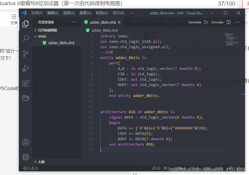
VSCode編輯
下載一個VHDL外掛就好,VSCode的介面看著很舒服

library ieee;
use ieee.std_logic_1164.all;
use ieee.std_logic_unsigned.all;
--註釋
entity adder_8bits is
    port(
        A,B : in std_logic_vector(7 downto 0);
        CIN : in std_logic;
        COUT: out std_logic;
        DOUT: out std_logic_vector(7 downto 0)
    );
    end entity adder_8bits;


architecture BIG of adder_8bits is
    signal DATA : std_logic_vector(8 downto 0);
    begin
        DATA <= ('0'&A)+('0'&B)+("00000000"&CIN);
        COUT <= DATA(8);
		DOUT <= DATA(7 downto 0);
    end architecture BIG;
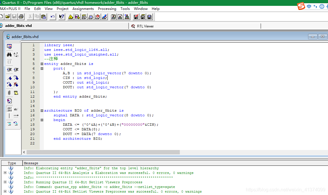
Quartus II編譯
輸入程式碼,選擇Processing > start > Analysis & Elaboration

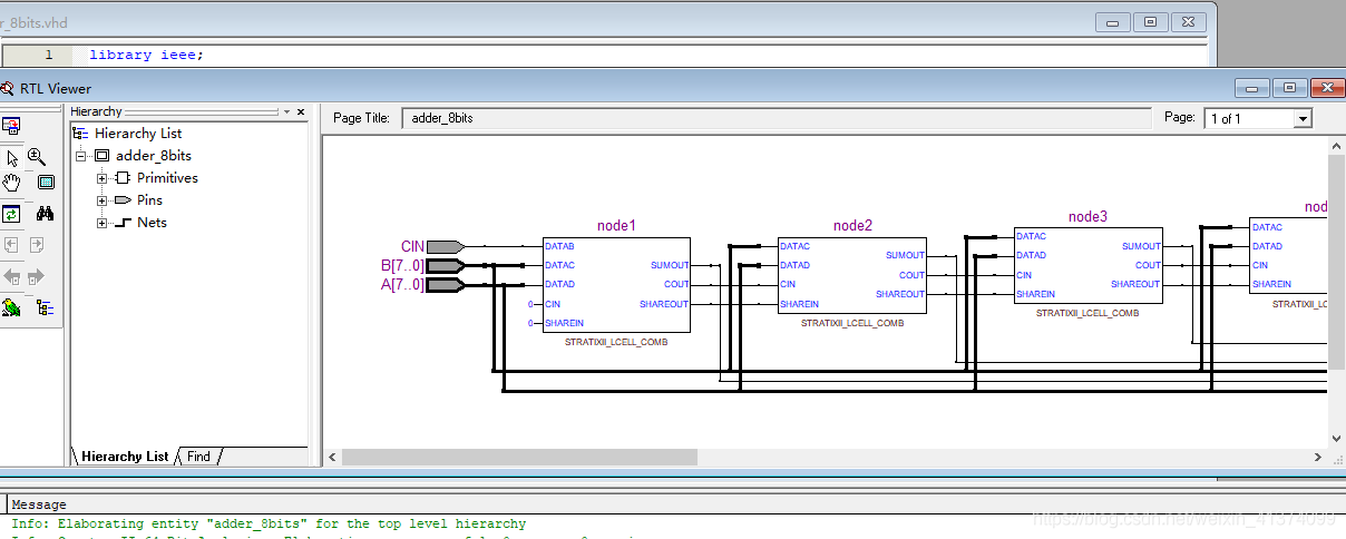
檢視RTL電路圖
Tools > Netlist viewer > RTL viewer
